In the previous part of this article series, we discussed how energy harvesting devices can help in increasing battery life. We discussed the basics of an energy harvesting system, energy harvesting devices and energy storage devices. In this last instalment of our article series, we will talk about Energy harvesting Power Management Integrated Circuits (EH PMIC).
Energy harvesting Power Management Integrated Circuits
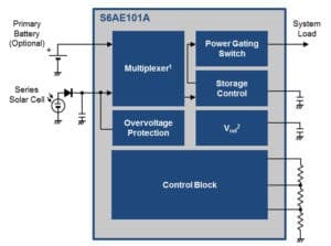
Energy harvesting devices provide intermittent output. Energy harvesting PMIC takes that intermittent output and provides a stable output voltage that can be used to power an IoT device. Figure 1 shows the high-level block diagram of a low-power, single-chip PMIC, S6AE101A from Cypress Semiconductor that can be used with solar cells.

Figure 1: Block diagram of solar-optimized power management integrated circuit
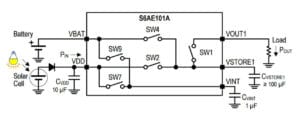
As shown in the block diagram, this PMIC not only takes the solar energy as input, but a primary battery can also be connected. Multiplexer switches between the two, based on the solar cell output. The primary battery is used only when there is not enough illumination and the solar cell is unable to provide enough energy output. As the primary battery is supplying the load when solar energy is available, the effective life of battery increases. Figure 2 shows the power delivery circuit of this device.

Figure 2: Power delivery circuit
As shown in figure 2, it integrates a power gating switch (SW1), a power storage switch (SW2), and a solar cell/battery changeover switch (SW4). Switches SW7 and SW9 are used to charge a capacitor (CVINT) that drives the internal circuit. SW7 turns ON when operating with the power source of the solar cell. SW9 turns ON when operating with the power source of the battery. Power provided by a solar cell is stored in CVSTORE1 via SW2. SW1 is turned on when the VSTORE1 voltage is within the range of the maximum and minimum VOUT voltage, and the power is applied to a load. When power is not generated by a solar cell, power from the connected battery is supplied to CVSTORE1 via SW4.
A given energy harvesting PMIC can connect to one or more type of energy harvesting devices based on the architecture. Selection of an appropriate energy harvesting PMIC is the key to a low-cost, small-system-footprint and efficient energy harvesting system. Energy harvesting PMICs can be divided into two categories – buck converter and boost converter.
Buck converter – PMICs based on this topology are mainly used with series connected solar cells and piezoelectric generator that produce an output voltage that is generally much higher than the required supply voltage of the load.
Boost converter – This type of PMICs are mainly used with the thermoelectric generator or single solar cell. In these transducers, the output voltage is just a few volts. Moreover, at lower temperature gradients and lower illumination levels respectively, for a thermometric generator and solar cell, this voltage can be 0.5V or lower. So, a boost converter topology is used to bring this output to a level that can power system load.
Some of the PMICs come with an integrated full-wave rectifier that is essential for piezoelectric and electromagnetic generators that produce an AC output. It eliminates the need of external components for these types of transducers. Also, it is important to examine input and output voltage range, maximum input and output current, start-up voltage and quiescent current specifications.
Adding Energy Harvesting to Internet of Things
Figure 3 shows the example of a solar + primary battery powered wireless sensor node. In most energy harvesting systems, though the system can deliver required average power, it may not meet peak power requirements and hence require special attention. It can be considered similar to designing a system to work with a coin cell battery. All methods explained in this series from Part 2 to Part6 are applicable on a system that uses energy harvesting.

Figure 3: Solar powered wireless sensor node
For a reliable energy harvesting system, it is also important to calculate appropriate size of capacitor that can store required amount of charge to power the load. Application note Energy Calculation for Energy Harvesting can be referred to, in order to find out the method to calculate energy requirements and capacitor size.
Conclusion
Designing an IoT device using batteries imposes various challenges for system designers due to limited capacity and limited peak power that they can deliver. Other challenges come into the picture from end user perspective and they are higher running cost, battery replacement due to physical limitation and waste management. To address these challenges, the system must be optimised for average and peak current consumption. Various techniques suggested in this article series can help improve power optimisation in each Bluetooth Low Energy (BLE) state. Beyond that, various system resources like CPU, peripherals, clocks etc. must also be optimised for power consumption. Energy harvesting system can further increase battery life by offloading battery when a renewable energy source is available. An energy harvesting system reduces the number of time battery needs to be replaced during product’s life span and also, maintenance cost is reduced. Appropriate selection of energy harvesting device, energy storage device and power management IC are important to implement an IoT application with efficient and low-cost energy harvesting system.


